You have a solid model for a large enclosure, a shroud, or a guard. The injection molding quote comes back at roughly $200,000 for the tool and fourteen weeks before you see a first article. Your annual volume is four hundred parts. The math does not work, and the program slips while you look for another path.
This is where thermoforming tooling earns its place. The tool is the single biggest variable in whether a large plastic part program is economically viable, and it is the decision most engineers make with the least information. Get the tool material right and you hit your launch date at a fraction of the capital. Get it wrong and you either overspend on a tool that outlives the program or buy a cheap tool that cannot hold tolerance past part three hundred.
What follows is how to choose.
What is thermoforming tooling, and why is it only half a mold?
Thermoforming heats a flat thermoplastic sheet to a pliable temperature, then forms it against a single-sided tool using vacuum, pressure, or both. The sheet drapes over or drops into one tool face. Vacuum evacuates the air between the sheet and the tool, and atmospheric pressure forces the material to conform.
That word "single-sided" is where the cost advantage comes from. Injection molding requires a matched male and female mold set built to withstand injection pressures, with gates, runners, ejector pins, and often moveable sections to clear undercuts. Thermoforming needs one tool face. Metal stamping needs a punch and a die. You are buying roughly half the tooling.
The sheet thickness matters here too. Heavy-gauge thermoforming works with thermoplastic sheet ranging from 0.060 inch to 0.50 inch, which is the range that produces structural parts capable of replacing fabricated metal. Thin-gauge forming, the process behind clamshells and disposable packaging, is a different discipline with different tooling economics.
Male or female tool: which surface do you need to control?
This distinction gets stated backward more often than it gets stated correctly, and it drives your tolerance strategy.
A male tool, sometimes called a positive or convex tool, controls the inside surface of the part. The sheet drapes over it. Your interior dimensions are dictated by the tool; the exterior surface is a function of the interior dimension plus whatever the sheet thickness happens to be at that location.
A female tool, or negative or concave tool, controls the outside surface. The sheet is pulled into the cavity, so the exterior geometry is dictated by the tool and the interior floats with material distribution.
The design question is simple: which surface has to fit something? If the part slips over an existing weldment or frame and the interior clearance is critical, you want a male tool. If the part has to sit flush in an opening or mate to an adjacent panel on the show surface, you want a female tool.
Wall thickness follows from the same choice. On a male tool, the sheet touches the top of the form first and stops stretching there, so material thins as it draws down the sidewalls. On a female tool, the sheet touches the cavity rim first and thins toward the bottom corners. Draft angles differ as well. Parts shrink onto a male tool as they cool and away from a female cavity, so male tools generally need more draft, commonly in the five to seven degree range, while female tools can often run two to three degrees. Confirm the numbers with your toolmaker against your specific geometry and material rather than treating them as fixed.
Which thermoforming mold material fits your production volume?
Tool material is a volume decision before it is anything else. The question is not which material is best. It is how many parts you need, over how many years, at what surface quality.
| Tool material | Realistic part life | Typical build time | Best fit |
|---|---|---|---|
| Wood and MDF pattern | A dozen to roughly 100 parts | 1 to 2 weeks | Fit, form, and function prototypes |
| Machinable tooling board | Low thousands | 2 to 4 weeks | Bridge tooling, low-volume production |
| Binder jet 3D printed | Up to roughly 5,000 parts | 1 to 2 weeks | Short-run production, complex geometry |
| Composite and epoxy | Thousands | 3 to 6 weeks | Low volume, seamless large surfaces |
| Cast aluminum | Tens of thousands | 8 to 12 weeks | Multi-year production programs |
| Machined aluminum, temperature controlled | Tens of thousands | 8 to 12 weeks | High volume, tight tolerance, fast cycles |
| Steel and ceramic | Very high | 12 weeks and up | Specialized cases, rarely justified in heavy gauge |
Wood and MDF patterns
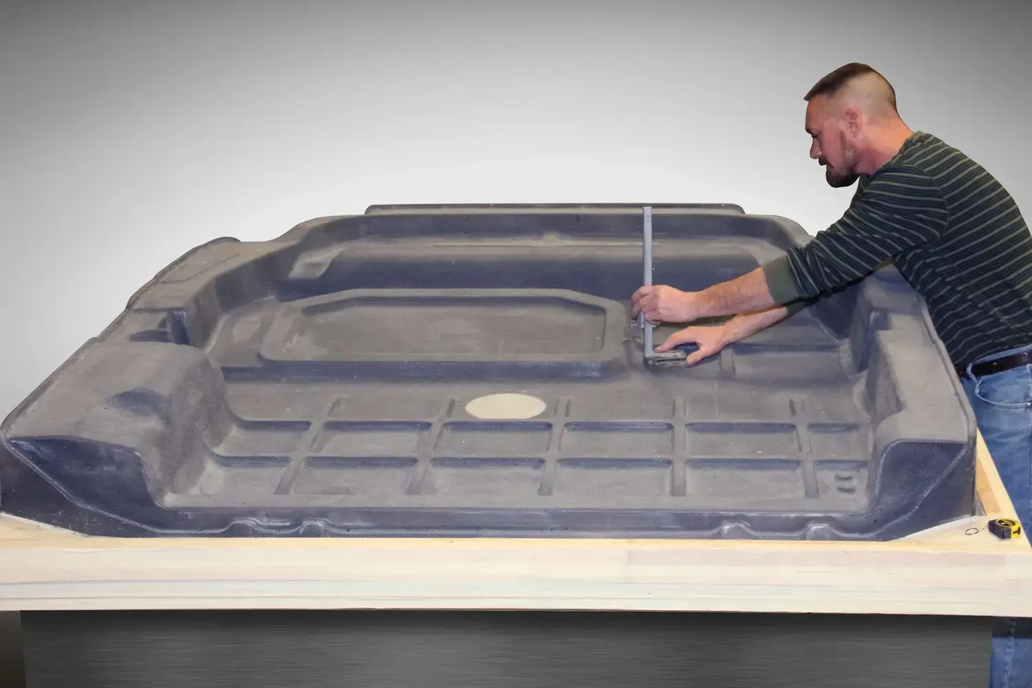
Laminated wood is the least expensive way to get real parts in hand. A wood pattern lets you produce roughly a dozen test parts, sometimes closer to a hundred with careful handling, which is enough to run fit, form, and function testing before anyone commits capital. Wood is easy to modify. A designer who wants a radius changed can have it changed the same week.
The limits are real. Wood dissipates heat poorly, which stretches cycle time, and it is prone to warping and splitting under repeated thermal loading. Nobody should be running production on a wood tool, and the honest answer is that nobody needs to. See how PCI uses low-cost patterns to build prototype parts before production tooling is committed.
Machinable tooling board
Tooling board occupies the middle ground where most low-volume industrial programs live. It produces parts in the low thousands, machines quickly, and takes revisions well. When a program is still moving, a tooling board mold that can be recut in a few days is worth more than an aluminum tool that locks in a design you are not finished with.
The tradeoff engineers should know about ahead of time is seam lines. Tooling board comes in blocks that get bonded together for large tools, and on smooth, high-gloss surfaces those bond lines can telegraph into the part. That is a tool design problem with tool design solutions, including seam placement in low-visibility areas or specifying a textured sheet. It needs to be raised during quoting, not discovered at first article.
Binder jet 3D printed tools
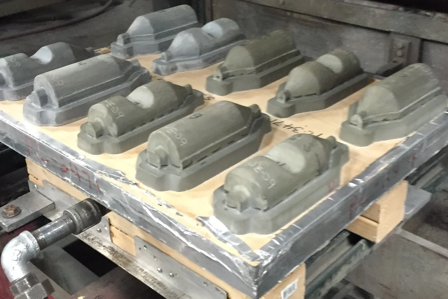
Additive tooling has moved past the prototype-only reputation. Binder jet printed tools handle short-run production up to roughly five thousand parts with ABS, PVC, and common blends, at pricing comparable to tooling board and on shorter timelines. The porosity of a binder jet tool can even work in your favor for vacuum distribution.
Size is the constraint. Print envelopes cap out well below the six by ten foot forming capacity of a heavy-gauge machine, so very large parts fall outside the process. Published durability figures also vary widely across the industry depending on resin system, sheet temperature, and gauge, so treat any single number as a starting point for a conversation rather than a specification.
Composite and epoxy tools
Fiberglass and epoxy composite tools are cast from a negative rather than machined from a block, which means no bond lines and no seam telegraphing on the part surface. They carry a high strength-to-weight ratio and hold up well to wear. For large, sweeping, cosmetically visible surfaces at low to moderate volume, a cast composite tool solves a problem that machined board cannot.
Cast and machined aluminum
Aluminum is where production tooling ends up when a program has legs. It handles tens of thousands of cycles, resists corrosion, tolerates high temperatures, holds tight machining tolerances, and reproduces fine detail, including logos and texture, that softer tools blur. Tools built with removable inserts are almost always aluminum, because inserts require tolerances the softer materials cannot hold.
The reason aluminum wins on high-volume work is thermal, not structural. MIC-6 cast aluminum plate spec sheets put thermal conductivity at roughly 142 W/m·K, and wrought 6xxx plate typically runs in the 150 to 170 W/m·K range. Tooling board and composite are an order of magnitude below that.
Steel and ceramic
Steel molds are durable and hold precision on large, complex geometry, but the cost and lead time rarely pencil out in heavy-gauge thermoforming, where forming pressures are a small fraction of what injection molding demands. Ceramic has a place in specific high-temperature applications. Both are worth discussing when the application genuinely calls for them, and both are the exception rather than the pattern.
For a deeper breakdown of how tool choice maps to program stage and annual volume, see tooling investment by production volume.
Why does tool material change your cycle time and part price?
In an automated heavy-gauge work cell, cooling time is usually the factor that sets overall cycle time. It is also the factor with the most room for improvement, and it traces directly back to the tool.
Water-cooled aluminum tool compared to a non-cooled tooling board tool can cool a part up to 5x faster, which changes throughput and per-part price across a multi-shift run.
That is not a marginal gain. Across a multi-shift production run, the cycle time reduction compounds into throughput that changes the per-part price, which is why the correct way to evaluate an aluminum tool is total cost per part over program life, not tool cost in isolation.
The trap is basing cycle time on how long a cheap mold takes to cool between shots. On a prototype or a low-volume run, the extra capital for temperature control is not worth it. On high-volume, multi-year production, a well-designed water-cooled aluminum tool pays for itself in throughput.
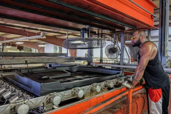
How much does thermoforming tooling cost compared to injection molding?
A typical heavy-gauge thermoforming toolset runs $10,000 to $50,000. Comparable injection molding or metal stamping tooling for a part of the same size starts around $150,000 and climbs. Put another way, thermoforming tooling generally lands at roughly ten to fifteen percent of equivalent injection mold tooling cost. Against a metal two-cavity press or die tool, thermoforming tool savings can exceed fifty percent.
Amortization is where that gap becomes a business case. At one thousand parts per year, a $25,000 thermoforming tool carries $25 per part in first-year tooling. A $200,000 injection mold carries $200 per part. The injection mold eventually wins on piece price at high enough volume, but for programs running in the tens, hundreds, or low thousands of units per month, the tooling differential is usually the entire decision. That crossover point is worked through in detail in when lower volumes make more sense than injection molding, and part-level pricing is broken out in how much heavy-gauge thermoforming costs.
How long does thermoforming tooling take to build?
Prototype tooling in wood, tooling board, or printed media typically runs one to four weeks. Some wood tools come together in days. Ceramic and aluminum production tooling generally runs eight to twelve weeks. Add time beyond first article if the part needs CNC or robotic trim fixturing or secondary assembly fixtures, which is common on large parts.
Injection mold tooling typically takes twelve to sixteen weeks and often longer. That difference is why thermoforming keeps launch dates that would otherwise slip.
Tools are also easier to revise. A change to a tooling board or wood mold is a recut, not a rebuild. When engineering change orders are still landing, that flexibility protects the schedule.
Can a thermoformed part really replace a steel one?
This is the objection worth addressing directly, because it is the one that stops most conversions before they start.
A heavy equipment OEM had a drive belt guard fabricated in steel. The belt required daily inspection, and the guard weighed roughly 718 pounds, too heavy for one person to lift. The crew brought a forklift over every time the belt needed service. The OEM wanted the redesigned product on a trade show floor in under three months.
718 lbs to 38 lbsA 95 percent weight reduction converting a steel belt guard to impact-resistant ABS. One person removes it now instead of a forklift crew, and equipment service time was cut in half.
First article prototypes were hand-delivered three weeks ahead of the show.
The conversion was not automatic. Specifications, testing, durability, aesthetics, and accessibility all had to be verified against the original, and the part carried the OEM's logo and branding molded in. What made the schedule work was tooling built in-house alongside the engineering, so the 3D solid model review, the tool, and the initial samples for Level 3 PPAP moved as one process instead of three handoffs.
The honest limits still apply. Thermoformed parts hold looser tolerances than injection molded parts and carry different structural properties than steel. The path forward is validation against your actual load cases and environment, not a blanket claim. More conversion economics are covered in replacing metal parts with thermoformed plastics.
How do you avoid buying the wrong tool?
Most tooling mistakes come from treating the decision as one-time. It rarely is.
The pattern that works on industrial programs is phased. Start with a wood or printed pattern to prove fit, form, and function against real assemblies. Move to tooling board or composite for bridge production and early customer shipments while the design settles. Commit to aluminum only when volume, program life, and cycle time economics justify it, and when the design has stopped moving.
Each phase buys information the next phase needs. Committing to aluminum before a design is frozen is how programs end up paying for the same tool twice.
The other half is supplier structure. When tool design, pattern making, casting, engineering, and forming sit under one roof, a dimensional problem found at first article gets corrected in days. When those functions are spread across three vendors, the same problem costs weeks of coordination.
Frequently asked questions
What is thermoforming tooling made of?
Thermoforming tools are built from wood and MDF, machinable tooling board, binder jet 3D printed media, cast composite and epoxy, cast or machined aluminum, and occasionally steel or ceramic. The choice is driven by production volume, required surface quality, cycle time targets, and program life.
How much does a thermoforming mold cost?
A typical heavy-gauge thermoforming toolset costs $10,000 to $50,000, compared to $150,000 or more for comparable injection molding or metal stamping tooling. Cost varies with part size, tool material, surface requirements, and whether temperature control is included.
How long does it take to make a thermoforming mold?
Prototype tools in wood, tooling board, or printed media take one to four weeks. Aluminum and ceramic production tooling takes eight to twelve weeks. Injection mold tooling typically takes twelve to sixteen weeks or longer.
What is the difference between a male and female thermoforming mold?
A male tool controls the inside surface of the part and requires more draft, commonly five to seven degrees. A female tool controls the outside surface and can often run two to three degrees of draft. Choose based on which surface has to fit or mate to something.
How many parts can a wood thermoforming tool produce?
A wood or MDF pattern typically produces a dozen to roughly one hundred parts. That is enough for fit, form, and function testing, not for production.
Why is thermoforming tooling cheaper than injection molding tooling?
Thermoforming forms a heated sheet against a single-sided tool using vacuum and low pressure. Injection molding requires a matched two-piece mold built to withstand high injection pressures, with gates, runners, ejector pins, and often moveable sections. You are buying roughly half the tooling in a softer material.
Can thermoformed plastic parts replace fabricated metal parts?
Yes, in many structural applications. One heavy equipment belt guard converted from steel to impact-resistant ABS dropped from 718 pounds to 38 pounds, a 95 percent weight reduction, and cut equipment service time in half. Conversion requires validating specifications, durability, and tolerances against your actual application.
How big can a thermoformed part be?
Heavy-gauge forming capacity at PCI runs up to six feet by ten feet with CNC trim, in sheet gauges from 0.060 inch to 0.50 inch.
Talk through your tooling before you commit capital
Send a solid model, a print, or the existing metal or fiberglass part, and you will get back a quote covering tool material recommendation, prototype path, production tooling, materials, and timing. If the right answer is a $12,000 board tool instead of an aluminum tool, that is what you will hear.
Send .STP files, SolidWorks native files, prints, or existing parts to info@plasticcomponentsinc.com.
Ready to Get Started? Request a QuotePlastic Components, Inc. has been forming large, heavy-duty thermoformed plastic parts in Elkhart, Indiana since 1972, with tooling, engineering, and manufacturing under one roof. Forming capacity runs to six feet by ten feet with CNC trim in ABS, HDPE, HMWPE, polycarbonate, polystyrene, PVC, TPO, nylon, TPR, and laminates, including co-extruded materials specified for UV stability, flammability, toxicity, and impact strength.
One of the most important advantages of the thermoforming process is the ability to make low-cost tooling leading to shorter lead times.
Where thermoforming tooling fits in the overall process
The thermoforming process can be broken up into four main steps:
1. Heating the material.
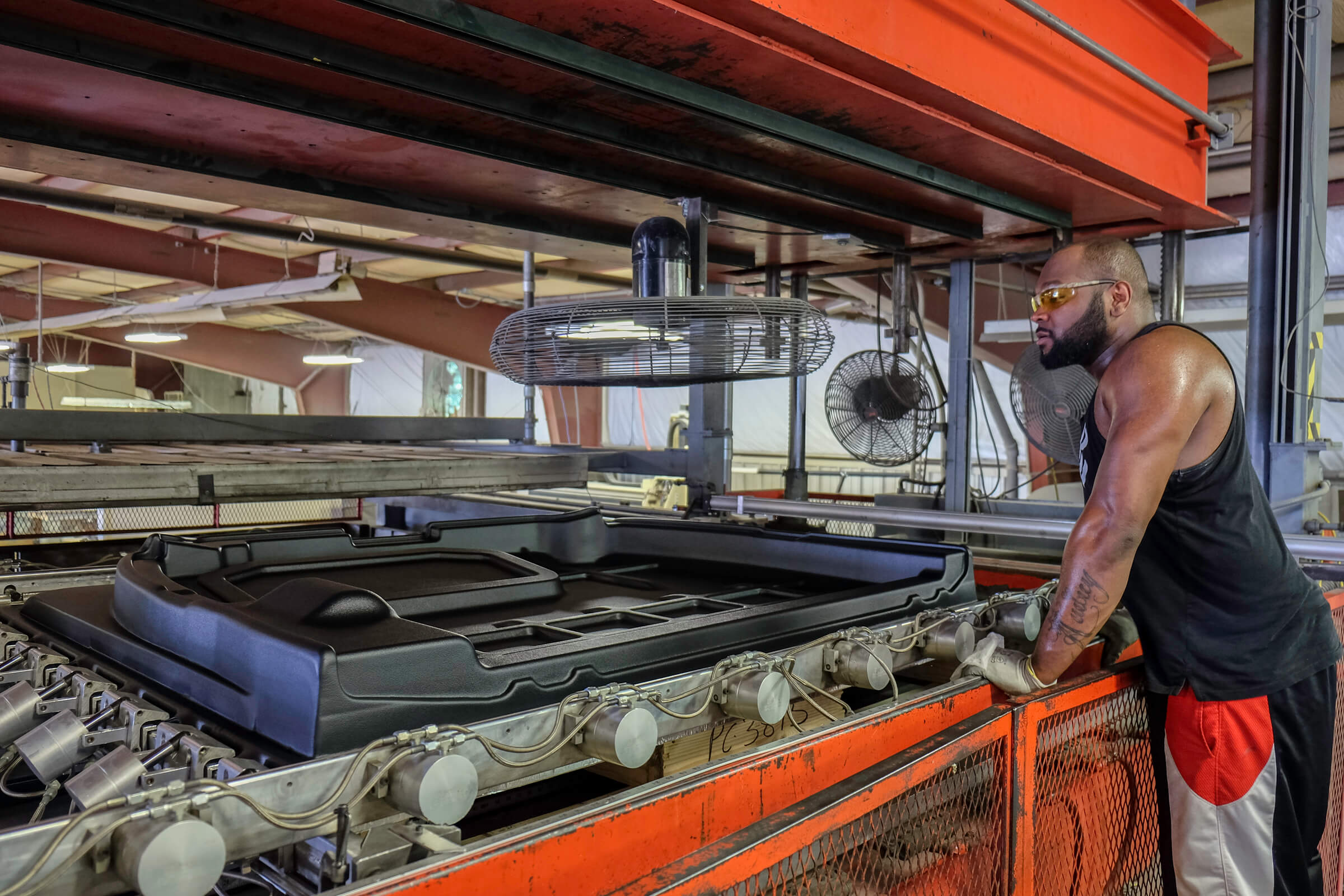
2. Forming the material. The heated flat plastic sheet material is molded into the desired shape using vacuum forming. Once the material is heated to moldable temperature, the material is stretched over a male mold or laid into a female, and then a vacuum is used to remove the air between the material and the mold. The removal of the air forces the material to conform to the shape of the mold.
3. Cooling the formed part.
4. Trimming the formed part.
Types of tooling available
All thermoforming tool consists of a positive tool that is convex-shaped and a negative tool that is concave-shaped. After heating the plastic sheet it is placed above the positive tool which will impart the exterior surface shape to the part. The negative tool gives the parts their outer surface shape.
Once formed, the plastic is cooled by using air or liquid cooling systems.
The material used to make the tool makes a big difference in the time to cool the part as well as affecting the final quality of the part.
A variety of tooling options are available depending on part design, specified sheet, and volume requirements.
We build thermoforming tooling using the following materials:
- Wood patterns
- 3D print
- Composite
- Ceramic
- Cast Aluminum
- Temperature Controlled Cast Aluminum
Using the above materials to make tools yields prototype part volumes ranging from 1 - 10 prototypes for wood patterns to multiple thousands using aluminum or temperature-controlled tooling.
Wood, composite, and 3D printed tools will produce prototype parts made from ABS, PVC, and blends. Ceramic and aluminum tooling can make production parts for most all thermoformable materials
Wood, composite, and 3D printed tools require 1-4 weeks lead time to build depending on the design complexity.
Ceramic and aluminum tooling require an 8-12 weeks lead time to build depending on the part size, shape, and detail.
Benefits of Thermoforming Tooling
Here is an example of the process of building thermoforming tooling and how it delivered the desired results for one of our customers.
"To start, PCI evaluated the 3D solid model design, machined tooling, and supplied initial samples for the level 3 PPAP.
A huge reason we chose PCI is that they machine various types of patterns, production tools, and production fixtures in-house. We know from hard-earned experience that molding houses that outsource their tooling design and production often have longer lead times and struggle to react quickly when something needs to be changed. And we all know that something always needs to be changed.
PCI is able to modify tools used in thermoforming quickly by either milling out an area to add a pocket or even adding material to a section to bring the tools into the desired state for the production run.
By turning around tooling fast, coupled with the inherent reduced cost of thermoforming tools, PCI saved us a ton of money when compared to sheet metal stamping tools.
We launched our commercial wall panel project quickly and needed to get the first prototypes fast. PCI was able to get us the first round of prototype parts within 5 weeks. We even brought our test vehicle to their location to test the quality of those initial prototypes and to make any adjustments.
PCI and their team were very helpful in reducing the time it took to get from the first article prototype to the production stage. They really know how to make adjustments quickly with a minimum of iterations.”
Outcomes:
- Significantly faster tool lead times to meet the schedule to get prototypes and first-run production parts to bring this product to market quickly.
- Significantly lower tool cost/capital investment - Decreased tooling costs by tens of thousands of dollars compared to other molding methods and metal stamping.
About PCI
Since 1972, Plastic Components, Inc. has been in the business of supplying heavy-duty and large thermoformed plastic parts to various industries and companies, including special vehicle, general industrial, mass transportation, telecom, agricultural, and truck/bus industries. We understand the value of time and money, so we design, assist in the design, engineer, and build tooling in-house.
Our in-house tool design, patterns, and castings capabilities allow us to build tools designed to meet your quantity, quality, and budget requirements.
Our knowledgeable and well-trained team works with you to ensure the end product meets or exceeds your specifications, regardless of the order size. Choosing PCI for your plastic needs will help you maximize the potential of your business.